Vortex motion in a quasi one-dimensional Josephson
junction array
This page shows solutions of the classical
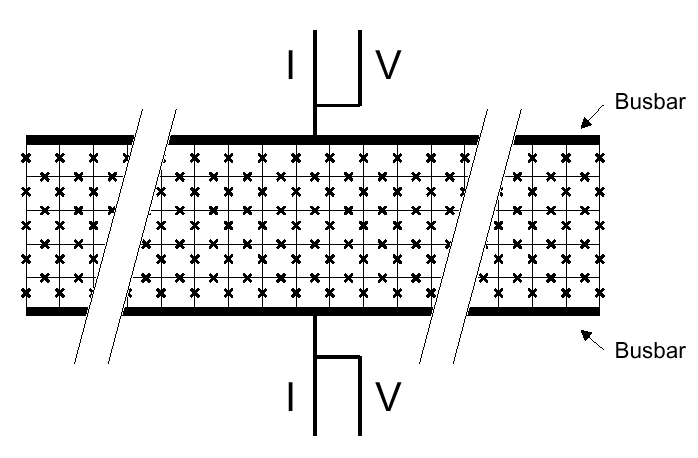
dynamics of the Josephson junction array shown in figure 1. The parameters
are chosen in the flux flow regime.

Figure 1: Schematic lay out of
a Josephson junction array for one-dimensional vortex motion. Josephson
junctions are represented by a cross, cells are areas enclosed by four
junctions. The arrays simulted have a length of 29 cells and a width of
5 cells between solid superconducting electrodes (busbars). Vortices
are induced by an applied magnetic field perpendicular to the array. They
are repelled by the busbars and forced to the middle row. Current is applied
vertically in the figure between the busbars, homogeneously along the length.
The current induces a potential gradient along the length. The motion of
vortices through the array creates a voltage across the array.
The Gauge chosen here is  .
.

Figure 2 a: Phase
configuration for 1.5 flux quanta applied to the total array . The Phases
of the islands are plotted with blue arrows. The black arrow indicates
the position of the vortex according to Eq. (1.4). The parameters are
f=1.5/(5*29),bc=1
and I=15 I0.

Figure 2 b: Current
distribution for 1.5 flux quanta applied to the total array. The Phases
of the islands are plotted with blue arrows. The black arrow indicates
the position of the vortex according to Eq. (1.4). The parameters are f=1.5/(5*29),bc=1
and I=15 I0.

Figure 3 a: Phase
configuration for six flux quanta applied to the total array. The Phases
of the islands are plotted with blue arrows. The black arrow indicates
the position of the vortex according to Eq. (1.4). The parameters are f=6/(5*29),bc=1
and I=10 I0.

Figure 3 b: Current
distribution for six flux quanta applied to the total array. The Phases
of the islands are plotted with blue arrows. The black arrow indicates
the position of the vortex according to Eq. (1.4). The parameters are f=6/(5*29),bc=1
and I=10 I0.

 .
.


